Foot throttle position sensor determines foot operated throttle position.This instruction show you guide on how to remove/install and test foot throttle position sensor for JCB 3CX/4CX/5CX backhoe loader.
Related Contents:
WinEEM4s JCB Service Tool 2.7.2 2.6.1 Free Download
2024 JCB ServiceMaster 4 v24.1.1 Free Download for Win 10 Win11
2017 JCB Parts Plus+ and Repair Service Manual Free Download
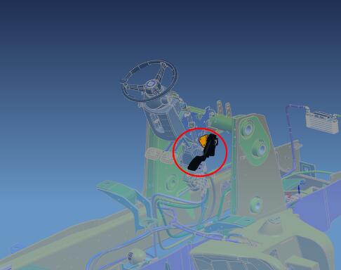
Location
The foot throttle pedal is vehicle mounted, normally on the right hand side of the cab adjacent to the driver’s foot.
The throttle position sensor (TPS) unit is located in the foot throttle pedal assembly.
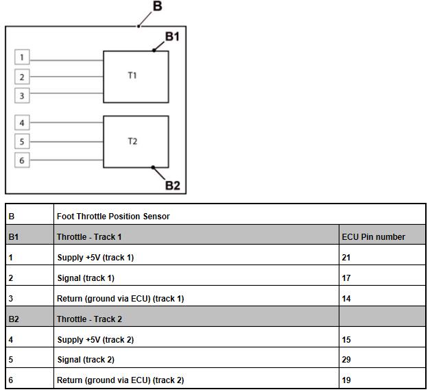
Signal
Analogue voltage driven by a 5V sensor supply within the engine ECU. The signal output should always be between 0.5V and 4.5V. The voltage output is proportional to throttle lever position. Two throttle tracks are used to ensure safety of the operator in the case of throttle malfunction.
Wires and Connectors
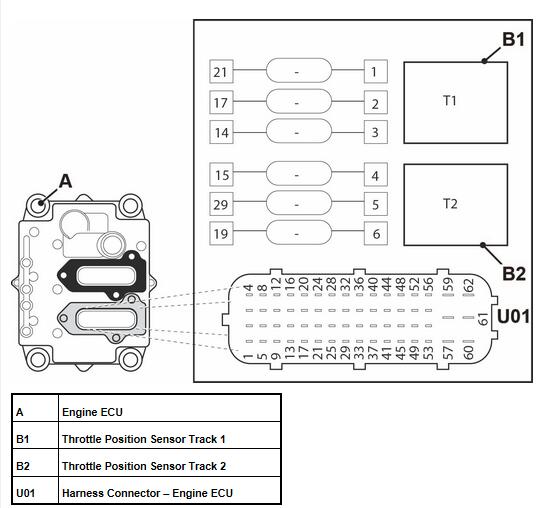
STOP: Before proceeding check all the relevant wires and connectors for integrity.
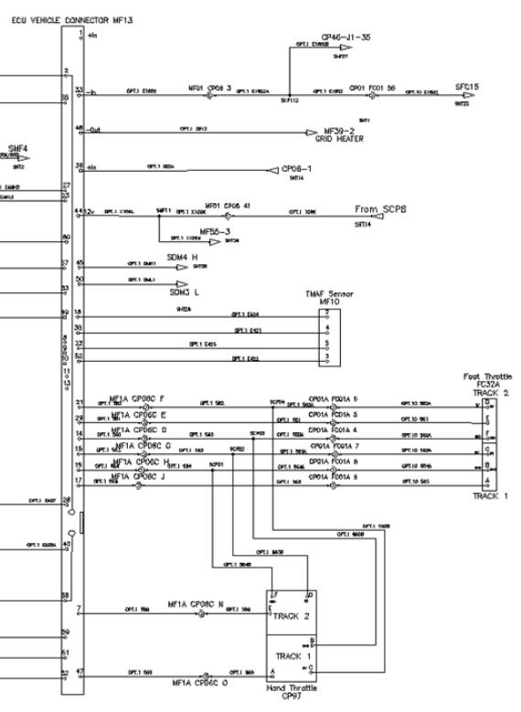
Internal Electrical Schematic
Remove and Install
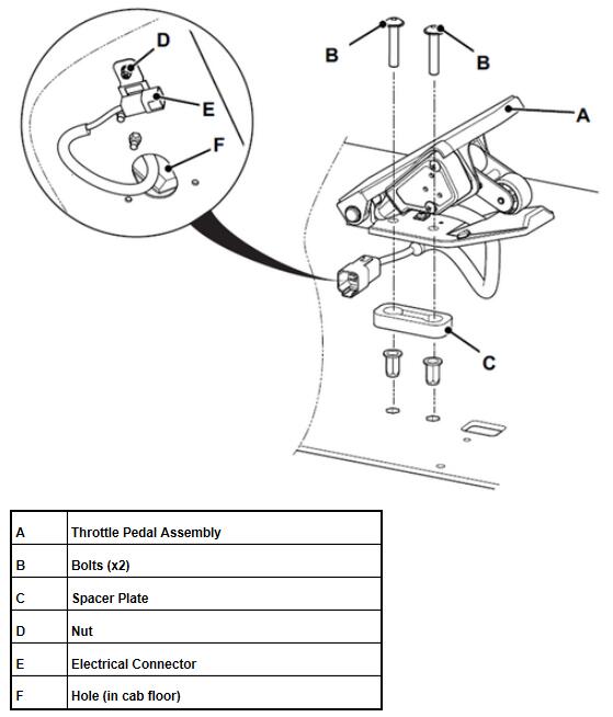
Remove
1 Make the machine safe and make sure it is switched OFF.
2 Remove the floor mat from the cab.
3 Work below the cab, disconnect the electrical connector from the chassis harness.
4 Remove the bolts.
5 Retain the spacer plate (if fitted).
6 Remove the nut to release the clip and electrical connector from the floor.
7 Slowly remove the throttle pedal assembly from inside the cab, make sure the electrical connector is pulled through the hole in the cab floor.
Install
Installation is the reversal of removal but note the following:
1 JCB threadlock and sealer is to be applied to the threads of the bolts.
Testing
Important: Use the multi-meter on the harness connector pins. DO NOT use the meter on the ECU pins.
1 Disconnect the sensor.
2 Switch the ignition ON.
3 Check supply voltage is 5 volts (pins 1 and 4). Connector pin 3 and 6 should read ground (0 volts).
4 If voltages are incorrect, check harness for continuity and ground conditions, check ECU pins for evidence of contamination or corrosion.
5 Measure signal voltage from the throttle position sensor when the throttle is at idle.
a)Pin 2 = 1.0 to 1.2 volts.
b)Pin 5 = 0.4 to 0.6 volts.
6Measure signal voltage when throttle is fully depressed.
a)Pin 2 – 4.0 to 4.5 volts.
b)Pin 5 – 2.2 to 2.5 volts.
Related Fault Codes
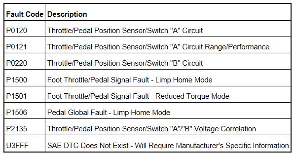
More repair case for JCB,please refer to:JCB Trouble Repair
How useful was this post?
Click on a star to rate it!
Average rating / 5. Vote count:
Please keep this link if you copy the post!
Related Posts
VCP System WABCO Programmer Active & Disable Start/Stop System for VW
2019.05.31
How to use Launch X431 IMMO to add a new key for Porsche Cayenne 2011-2017
2024.01.28

JCB StageV Tier4 Air Filter Pressure Sensor Active at Init State
2023.10.4
How to install TIS2000 and GlobalTIS for GM Tech2 Scanner
2022.03.22
Best Quality VCM II Diagnostic Tool With WIFI Function for Ford V98
2018.12.17
How to Access JLR SDD Engineering Mode (Seed Key)
2023.04.4
Bosch ADS625 Read & Clear DTCs for Volkswagen Passet GLS 2004
2019.07.19

How to Connect NEXIQ First-Link using Smartphone
2024.01.24

How to Identify Volkswagen Vehicle Immobilization Generations
2023.04.4
Buick LaCrosse PK-13 Chip Adding & All Key Lost Programming
2019.02.24