Diagzone Xdiag Subscription Renew, LAUNCH LTR-01 RF Sensor, Thinkdiag Renew , Scania SDP3 Installation
This instruction show you guide on how to decommission and commission electrical system for Volvo EC18 electric.
Preparation:
Volvo Prosis 2023 2022 2019 Free Download
Volvo Techtool 2023 Diagnostic Software
Volvo VOCOM 88890300
Procedures:
Protective gloves in different sizes are available as special tools.
A check of the measuring equipment must be carried out prior and after to measurement to ensure that valid values are measured. The review must be done on an independent system under known conditions.
The operation must only be carried out by personnel with adequate training to safety regulations.
1.Check the personal protective equipment prior to the work activity.
2.Establish a work location and place the machine in the defined area.
Decommissioning
3.Place machine in the service position.
4.Disconnect all charging equipment. See the instruction in the operator manual.
5.Turn the battery disconnect switch to the off position and secure it against restarting.
NOTE!
Use a LOTO device to secure the battery disconnect switch.
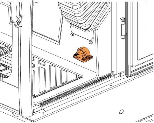
Figure 1
Battery disconnect switch
6.Open the rear hood (5).
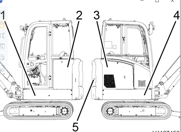
Figure 2
Covers
7.Remove the upper (2) and lower (1) left side cover.
8.Disconnect the cable from the negative (-) battery terminal (1).
NOTE!
It takes up to 10 minutes to discharge the electric energy.
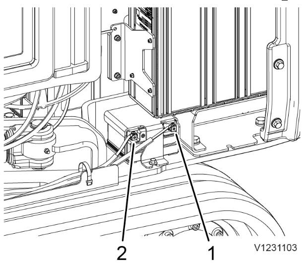
Figure 3
Battery
Negative (-) battery terminal
Positive (+) battery terminal
9.Put on required personal protective equipment.
10.Remove the cover of the fuse box.
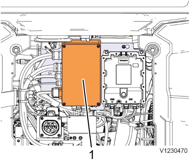
Figure 4
Fuse box
11.Measure the voltage free condition between the positive (+) cable (1) connected to the fuse box and the frame ground point or the negative (-) connector at the fast charging connector. Use 88830641 Test unit
NOTE!
Observe the correct handling of the test unit.
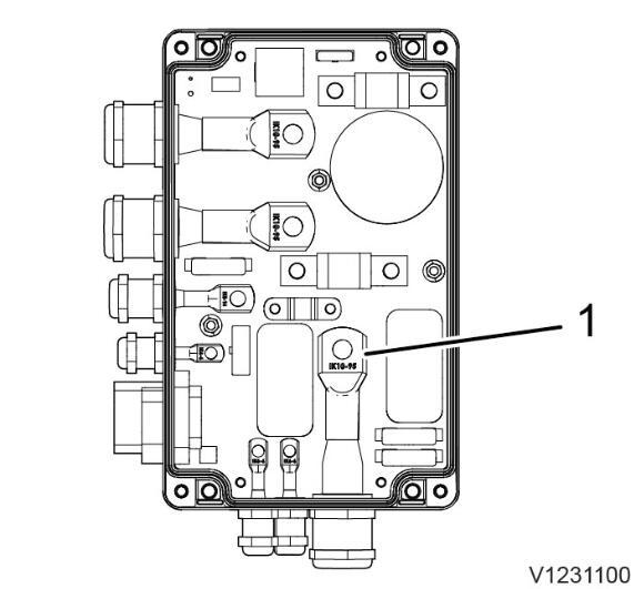
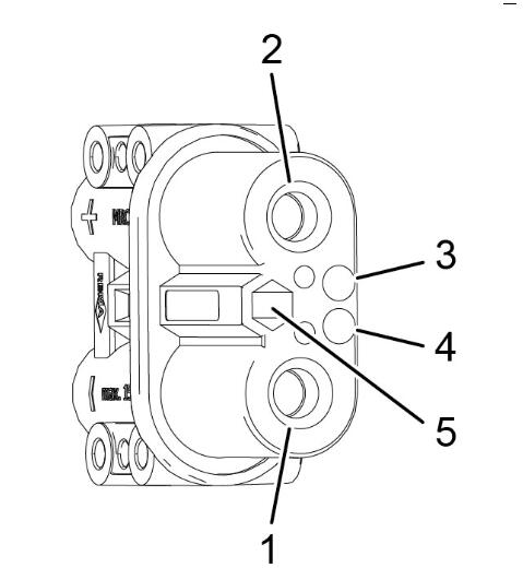
Figure 6
Fast charging connector
Negative (-) connector
Due to the compact installation situation of the batteries, there are two options to disconnect the supply voltage.
Variant 1
12.Remove the upper left side cover.
13.Disconnect the cables from the negative (-) battery connections (1).
NOTE!
Cover the connector of the cables to avoid undesired connection.
Figure 7
Traction batteries
14.Disconnect the cables from the positive (+) battery connections (2).
NOTE!
Cover the connector of the cables to avoid undesired connection.
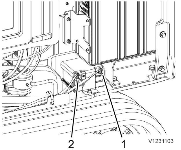
Variant 2
NOTE!
Consider that the positive (+) cables up to the fuse box may under live voltage if a malfunction of a battery occurs.
NOTE!
Do not proceed any operation in the proximity of these cables and the fuse box.
15.Disconnect the positve (+) cable from the terminal (1), use a protective cap to isolate it.
NOTE!
Secure that the protective cap isolates the cable.
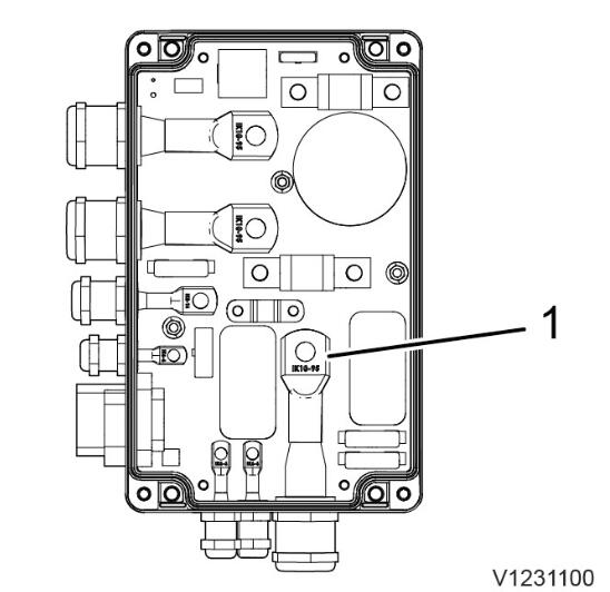
16.Install the fuse box cover and tighten the screws
17.Apply a sticker on the outside of the fuse box that mention the segregation takes place internally.
Commissioning
If not stated otherwise, follow the instructions below.
Variant 1
18.Install the cover of the fuse box.
19.Connect the cables to the positive (+) battery connections (2).
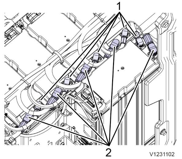
Figure 9
Traction batteries
20.Connect the cables to the negative (-) battery connections (1).
Variant 2
21.Remove the cover of the fuse box.
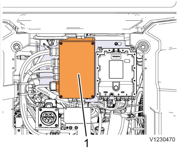
Figure 10
Fuse box
22.Remove the isolating protective cap on the cable.
23.Connect the positive (+) cable to the terminal (1). Tighten the screw of the terminal with recommended torque.
24.Install the cover of the fuse box.
25.Remove the applied sticker mentioning the segregation.
Common procedure
26.Connect the cable to the negative (-) battery terminal (1).
27.Close the covers.
28.Remove the LOTO device securing the battery disconnect switch.
29.Turn the battery disconnect switch to the on position.
30.Set the ignition switch to position 1.
NOTE!
Wait about 1 minute and check that no error messages appears.
Set the ignition switch to position 0.
For more Volvo excavator repair,please refer to Volvo excavator trouble repair
How useful was this post?
Click on a star to rate it!
Average rating / 5. Vote count:
Some Friends don't know how to activate win7, when they receive the diagnostic software with win7 sytem. http://www.chinaobd2.com/upload/software/win7activation.zip download this Read more
Please ensure that you choose computer systems that meet our requirements for the installation. You will find adetailed listing in Read more
Frequent oil changes are perhaps the most important procedure you can do to maintain and prolong the life of your Read more
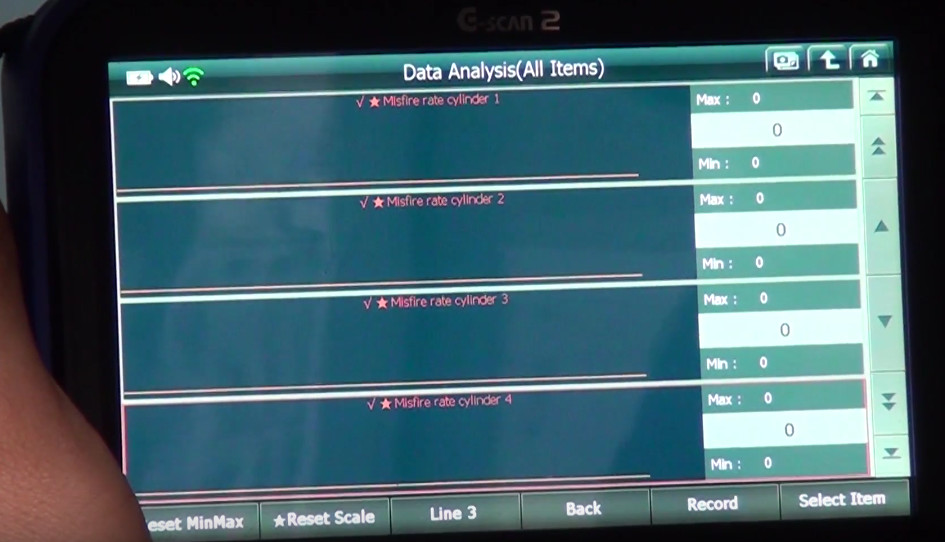
This article show a guide on how to use G-scan2
Please keep this link if you copy the post!