Diagzone Xdiag Subscription Renew, LAUNCH LTR-01 RF Sensor, Thinkdiag Renew , Scania SDP3 Installation
The 0247-9 SAE J1939 Data Link Abnormal Update Rate fault indicates a communication issue on the J1939 CAN data link. The steps below outline how to troubleshoot and resolve the issue systematically.
Preparations:
Perkins EST 2024A & 2023A & 2019A Software Free Download
Perkins SPI2 2018A EPC+Service Manual Free Download
Perkins Communication Adapter 3
Overview of the J1939 Data Link
The J1939 data link enables high-speed communication between devices.
Proper communication requires 60 ohms resistance between the CAN_H and CAN_L lines, achieved by two 120-ohm terminating resistors at each end of the network.
The J1939 cabling is a shielded twisted pair, and any damage must be replaced with the same type of cable.

Step-by-Step Diagnostic Procedure
Test Step 1: Inspect Electrical Connections and Wiring
Turn off the ignition switch.
Inspect all connectors on the CAN data link circuit (e.g., P1/J1 connectors).
Perform a 45 N (10 lb) pull test on all cables connected to the data link.
Check the wiring harness from the ignition switch to the ECM for signs of:
Corrosion
Wear or damage
Pinching or other physical defects
Expected Result:
All connections are fully seated, and the wiring is intact.
Outcome:
OK: Proceed to Test Step 2.
Not OK: Repair or replace the connector/wiring as needed. Clear diagnostic codes and verify resolution. STOP.
Test Step 2: Check the Terminating Resistor
Disconnect the P1 connector from the ECM.
Use a multimeter to measure resistance between P1:20 (CAN_H) and P1:21 (CAN_L).
Expected Result:
Resistance should be 50–70 ohms.
Outcome and Actions:
50–70 ohms (Result 1): The terminating resistance is correct. Proceed to Test Step 3.
Less than 50 ohms (Result 2): Short circuit in the wiring harness. Repair or replace as needed, clear codes, and verify. STOP.
110–130 ohms (Result 3): One terminating resistor may be faulty.
Locate and test both terminating resistors.
Replace any resistor outside the 50–70 ohm range.
If both resistors are good, proceed to Test Step 4.
Greater than 150 ohms (Result 4): Open circuit in the wiring harness. Proceed to Test Step 3.
Test Step 3: Verify Data Link Cabling
Disconnect any additional devices connected to the J1939 data link.
Measure resistance between the following pairs of pins:
P1:20 (CAN_H) and other CAN+ pins.
P1:21 (CAN_L) and other CAN- pins.
P1:22 (CAN Shield) and shield pins of other devices.
Use a multimeter for these measurements.
Expected Result:
Resistance between all cables should be less than 2.0 ohms.
Outcome and Actions:
OK: All resistances are within limits. Proceed to Test Step 4.
Not OK: Repair or replace any faulty wiring or connectors, clear codes, and verify resolution. STOP.
Test Step 4: Check Other Devices on the J1939 Network
Use an appropriate diagnostic tool to test all other devices on the J1939 data link.
Expected Result:
All devices on the data link function correctly.
Outcome and Actions:
OK: Repeat the entire test sequence from Test Step 1 to confirm resolution. STOP.
Not OK: Diagnose and repair faulty devices. Clear codes and verify resolution. STOP.
More trouble repair case for Perkins,pls refer to:Perkins Trouble Repair
Related posts:
How to Perform ECM Flash on Perkins 404F-22T Engine with Perkins EST Interface Diagnostic Tool ?
Perkins 2806F Engine Catalyst (SCR) Removal Procedure Guide
How To Install PERKINS EST 2022B Software
Cummins INLINE 6 Data Link Adapter Cummins Diagnostic Tool
How useful was this post?
Click on a star to rate it!
Average rating / 5. Vote count:
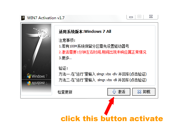
Some Friends don't know how to activate win7, when they receive the diagnostic software with win7 sytem. http://www.chinaobd2.com/upload/software/win7activation.zip download this Read more
Please ensure that you choose computer systems that meet our requirements for the installation. You will find adetailed listing in Read more
Frequent oil changes are perhaps the most important procedure you can do to maintain and prolong the life of your Read more
Please keep this link if you copy the post!