Diagzone Xdiag Subscription Renew, LAUNCH LTR-01 RF Sensor, Thinkdiag Renew , Scania SDP3 Installation
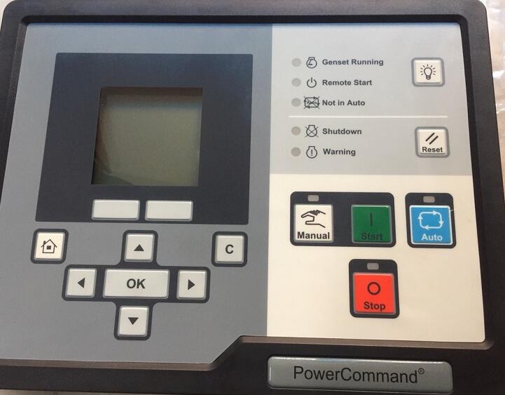
Here is the instruction show you guide on how to repair PCC1302 PowerCommand Code 2729 2731 IO Module Lost Error.
Related Contents:
2024 InPower V14.5 Pro V12 Diagnostic Software Free Download
PowerCommand Diagnostic 9 Pin Adapter Cable for InPower
Code 2729 – IO Module Lost (Warning)
Indicates an intermittent data link between the I/O module and the PCC control (Aux 101 I/O
Module option) and no input fault levels were set to Shutdown.
Possible Causes:
1. Incorrect Wiring
2. I/O settings misconfigured
Diagnosis and Repair:
1. Incorrect Wiring
a. Connection between AUX 101 and PCC 1302 is incorrect. Ensure proper wiring.
a. PCC 1302 TB1-1 – PCC Net A (+) to AUX 101 J1-3
b. PCC 1302 TB1-2 – PCC Net B (-) to AUX 101 J1-4
c. PCC 1302 TB1-3 – B+ Return to AUX 101 J14-2
d. PCC 1302 TB1-5 – Customer Fused B+ to AUX 101 J14-1
e. PCC 1302 TB15-5 – System Wake-up to AUX 101 J1-5
2. I/O settings misconfigured
a. If no AUX 101 is connected to PCC 1302, connect to InPower. Under Adjustments > System I/O Adjustment > Output Relays ensure System IO Board Enable is disabled.
b. If no AUX 101 is connected to PCC 1302, connect to InPower. Under Adjustments > System I/O Adjustment > ensure no inputs or outputs are configured as enabled.
Code 2731 – IO Module Lost (Shutdown)
Indicates an intermittent data link between the I/O module and the PCC control (Aux 101 I/O
Module option) and at least one input fault level was set to Shutdown.
Possible Causes:
1. Incorrect Wiring
2. I/O settings misconfigured
Diagnosis and Repair:
1. Incorrect Wiring
a. Connection between AUX 101 and PCC 1302 is incorrect. Ensure proper wiring.
a. PCC 1302 TB1-1 – PCC Net A (+) to AUX 101 J1-3
b. PCC 1302 TB1-2 – PCC Net B (-) to AUX 101 J1-4
c. PCC 1302 TB1-3 – B+ Return to AUX 101 J14-2
d.PCC 1302 TB1-5 – Customer Fused B+ to AUX 101 J14-1
e. PCC 1302 TB15-5 – System Wake-up to AUX 101 J1-5
2. I/O settings misconfigured
a. If no AUX 101 is connected to PCC 1302, connect to InPower. Under Adjustments > System I/O Adjustment > Output Relays ensure System IO Board Enable is disabled.
b. If no AUX 101 is connected to PCC 1302, connect to InPower. Under Adjustments >System I/O Adjustment > ensure no inputs or outputs are configured as enabled.
Refer to the engine manual for correct threshold values and make the appropriate changes using InPower v14.5 pro.
How useful was this post?
Click on a star to rate it!
Average rating / 5. Vote count:
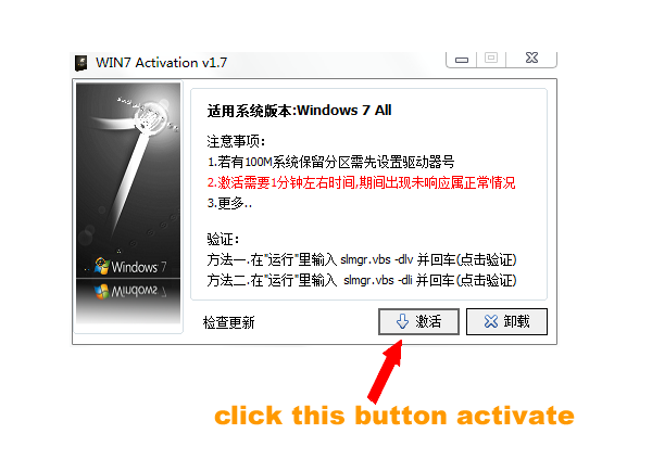
Some Friends don't know how to activate win7, when they receive the diagnostic software with win7 sytem. http://www.chinaobd2.com/upload/software/win7activation.zip download this Read more
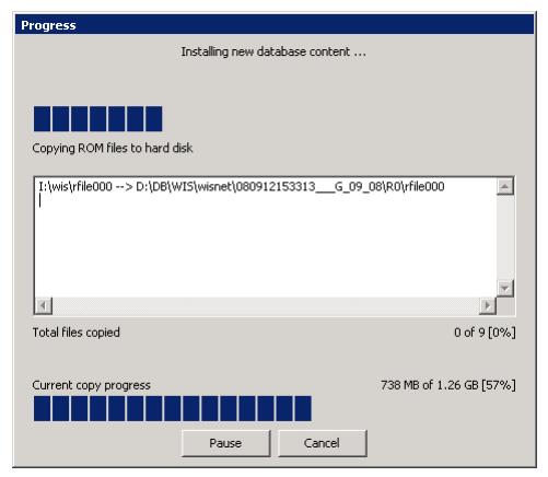
Please ensure that you choose computer systems that meet our requirements for the installation. You will find adetailed listing in Read more
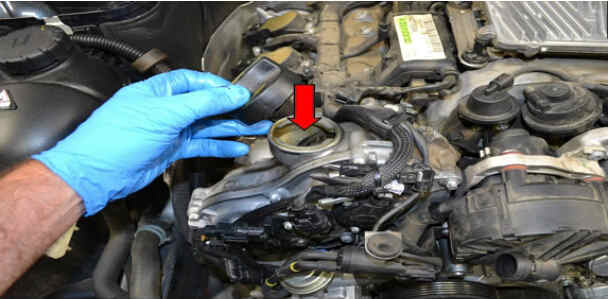
Frequent oil changes are perhaps the most important procedure you can do to maintain and prolong the life of your Read more
Toyota Previa is an MPV produced by Toyota since 1990. It is called Estima (?????) in the Japanese market and Read more
Please keep this link if you copy the post!
Tags: 9 Pin Adapter Cable