Diagzone Xdiag Subscription Renew, LAUNCH LTR-01 RF Sensor, Thinkdiag Renew , Scania SDP3 Installation
Here is an illustration show the details instruction on Kubota L3901 tractor engine sensors.
Related Contents:
2022 Kubota Takeuchi Diagmaster v22.08.01 v4.1.2 Software Free Download
Kubota EPC Spare Parts Catalogue 2021.06 Download
Kubota DST-I Diagnostic Tool
Crankshaft Position Sensor
The crank position sensor (1) is mounted on the flywheel housing and the sensor body uses a hall
element type.
When pulse holes (2) provided on the outer edge of the flywheel (4) pass through the sensor, the internal magnetic field changes and this is output to the engine ECU.
Also, a no hole part (3) is provided in a part and this detects the crank position each rotation and outputs this to the engine ECU.
The engine ECU uses the signals to calculate the crank angle and engine speed.
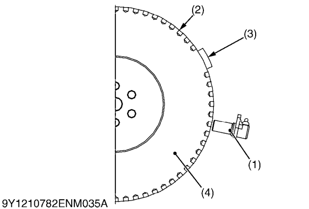

(1) Crankshaft Position Sensor (2) Pulse Hole
(3) Part without a Hole (4) Flywheel
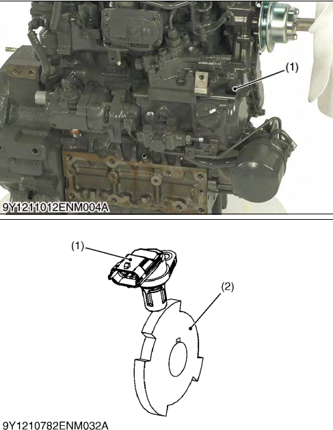
Camshaft Position Sensor
The cam position sensor (1) is mounted near the supply pump gear of the gear case and the sensor
functions in the same way as the crank position sensor.
This sensor detects the teeth of the pulsar gear (2) and the engine ECU uses this signal to calculate the cam angle.
(1) Cam Position Sensor (2) Pulsar Gear
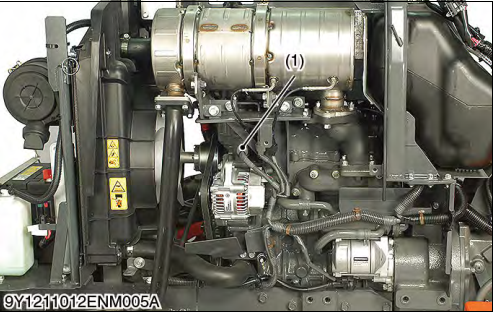
Coolant Sensor
The temperature sensor is mounted to the water flange and uses a thermistor in the sensor part to detect temperature.
A characteristic of thermistors is that their electrical resistance varies with temperature, and this
characteristic is used by the different sensors to detect temperature via voltage.
(1) Coolant Sensor
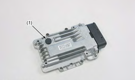
Atmosphere Pressure Sensor
An atmosphere pressure sensor is installed in the body of the ECU and detects atmospheric pressure close to the ECU.
This is provided to prevent changes to combustion status due to changes in atmospheric pressure. (At high altitudes, air pressure is low and air volume is low making complete combustion difficult etc.)
NOTE
How useful was this post?
Click on a star to rate it!
Average rating / 5. Vote count:
Please keep this link if you copy the post!
