Diagzone Xdiag Subscription Renew, LAUNCH LTR-01 RF Sensor, Thinkdiag Renew , Scania SDP3 Installation
Here is the instruction show you guide on how to assemble Kubota L3301 L3901 L4701 tractor hydraulic cylinder.
Related Contents:
2025 Kubota Takeuchi Diagmaster v25.02.01 Software Free Download
Kubota EPC Spare Parts Catalogue 2021.06 Download
Kubota DST-I Diagnostic Tool
Hydraulic Cylinder Assembly
1 Loosen and remove the hydraulic cylinder assembly mounting screws and nuts.
2 Support the hydraulic cylinder assembly with nylon lift strap and hoist, and then remove it.
(When reassembling)
Apply liquid gasket (Three Bond 1206C or equivalent) to joint face of the hydraulic cylinder assembly and transmission case after eliminate the water, oil and stuck liquid gasket.
When replacing the hydraulic cylinder assembly mounting stud bolts, apply liquid lock (Three Bond 1324 or equivalent) to (A) portion of the stud bolt.

NOTE
Reassemble the hydraulic cylinder assembly to the tractor, be sure to adjust the position control rod. (See page 8-S15.)
PTO Clutch and Pinion Bearing Holder
1 Remove the coupling (1) and the PTO clutch cam (5).
2 Remove the screws (3) and pinion bearing holder assembly (4).
3 Remove the lock nut (2).
(When reassembling)
Make sure of the number of shims in the pinion bearing holder.
Replace the lock nut (2) with a new one, and stake the lock nut firmly after installing the parts on the shaft.


Gear and Shaft Assembly
1 Remove the spacer mounting screws.
2 Separate the spacer (1) from the transmission case.
3 Remove the 16T gear shaft assembly (2).
4 remove the pinion shaft assembly (3) and PTO drive shaft assembly (4).
(When reassembling)
Apply liquid gasket (Three Bond 1206C or equivalent) to joint faces of spacer and transmission case.


Rear Axle Case
1 Loosen and remove the rear axle case mounting screws and nuts.
2 Support the rear axle case (1) with the nylon lift strap and hoist.
3 Separate the rear axle case from brake case.
4 Follow the same procedure as above for the other side.
(When reassembling)
Apply liquid gasket (Three Bond 1206C or equivalent) to joint face of the rear axle case and brake case, after eliminating the water, oil and stuck liquid gasket.

Brake Case
1 Loosen the remove the brake case mounting screws and nut.
2 Separate the brake case, tapping the brake case lever lightly.
(When reassembling)
Apply grease to the brake ball seats. (Do not grease excessively.)
Apply liquid gasket (Three Bond 1206C or equivalent) to joint face of the brake case and transmission case, after eliminating the water, oil and stuck liquid gasket.
Before installing the brake case to the transmission case, install the cam plate to the transmission case.
Apply liquid lock (Three Bond 1324 or equivalent) to (A), (B), (C), (D)portions of the stud bolts, R.H. and L.H..

Differential Lock
1 Remove the clevis pin (1).
2 Draw out the differential lock fork shaft (2).
3 Remove the shift fork (3).
More repair case for Kubota,please refer to:Kubota Trouble Repair
How useful was this post?
Click on a star to rate it!
Average rating / 5. Vote count:
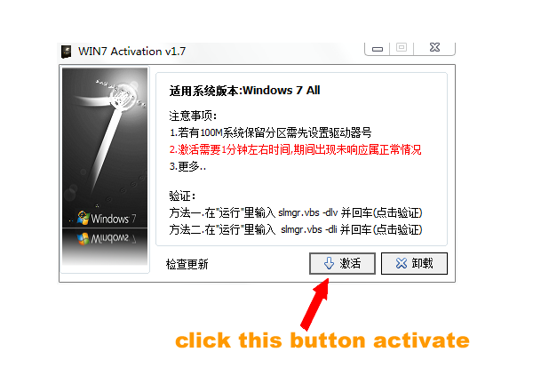
Some Friends don't know how to activate win7, when they receive the diagnostic software with win7 sytem. http://www.chinaobd2.com/upload/software/win7activation.zip download this Read more
Please ensure that you choose computer systems that meet our requirements for the installation. You will find adetailed listing in Read more
Frequent oil changes are perhaps the most important procedure you can do to maintain and prolong the life of your Read more
Please keep this link if you copy the post!