Diagzone Xdiag Subscription Renew, LAUNCH LTR-01 RF Sensor, Thinkdiag Renew , Scania SDP3 Installation
It is necessary to dismantle and assemble excavator valve control to finish service procedures for JCB 3CX 4CX backhoe loader excavator.So here come the details steps,hope it helps.
Related Contents:
WinEEM4s JCB Service Tool 2.7.2 2.6.1 Free Download
2017 JCB Parts Plus+ and Repair Service Manual Free Download
2023 JCB ServiceMaster 4 Free Download for Win 7/Win 8/Win 10
Dismantling and Assembly
Excavator Valve Controls
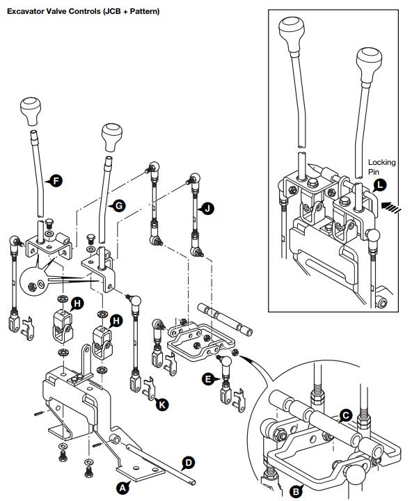
The illustration on the adjacent page shows the control rods and linkages for the excavator control valve and is intended as a guide to the dismantling and assembly. Note JCB + pattern controls shown.
Dismantling
1 Park the machine on firm level ground, apply the parking brake. Lower the loader arms, move the excavator to the R.H. side of the machine and lower to the ground. Switch OFF the engine and remove the starter key. Disconnect the battery.
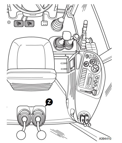
2 Working in the cab, remove the console panels surrounding the excavator levers as shown at Z.
3 Uncouple the rear horn switch electrical connector and remove the wires from the connector. Use a screwdriver to release the wires/pins from the connector, alternatively cut the wires and re-solder on assembly.
4 Remove the control lever knobs and gaiters.
5 Disconnect the control rods from the excavator valve spools. Remove the bolts securing the complete lever assembly to the excavator valve mounting plate and withdraw the control levers and mounting bracket through the floor aperture.
Assembly
Assembly is the reverse of the dismantling sequence.
1 Bolt the mounting bracket A to the excavator valve mounting plate.
2 Assemble the pivot levers B and spacers C to the mounting bracket and insert the pivot shaft D. Fit the short control rods E (2 off) to the pivot lever assembly as shown.
3 Assemble the excavator levers F and G to the mounting bracket together with the universal joints H. Fit the longer control rods J (4 off) to the lever assembly as shown.
Note: If necessary, loosen the lock nuts and rotate the end fittings to give equal amounts of adjustment (thread) at each end of the control rod.
4 Connect the control rods to the excavator valve spools with the clevis pins K.
5 Adjust the control rods as necessary, see Adjustment.
After the control rods are adjusted fit the gaiters over the control levers.
6 Thread the rear horn switch cable through the control lever and fit the wires/pins into the electrical connector.
Couple the connector to the chassis harness and fit the control lever knobs.
7 Connect the battery, check that the controls and rear horn switch operate correctly.
8 Refit the console panels around the excavator levers.
Adjustment
1 Fit the control lever locking pin L as shown.
Note: If there is no lever locking pin with the machine use a suitable diameter metal bar.
2 Adjust the control rods until the locking pin is a sliding fit, then tighten the control rods lock nuts.
Note: Make sure there is an equal amount of thread at each end of the control rod.
3 Remove the lever locking pin L.
More repair case for JCB,please refer to:JCB Trouble Repair
How useful was this post?
Click on a star to rate it!
Average rating / 5. Vote count:
Some Friends don't know how to activate win7, when they receive the diagnostic software with win7 sytem. http://www.chinaobd2.com/upload/software/win7activation.zip download this Read more
Please ensure that you choose computer systems that meet our requirements for the installation. You will find adetailed listing in Read more
Frequent oil changes are perhaps the most important procedure you can do to maintain and prolong the life of your Read more
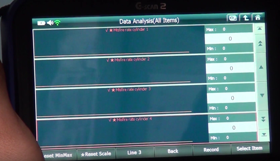
This article show a guide on how to use G-scan2
Please keep this link if you copy the post!