Diagzone Xdiag Subscription Renew, LAUNCH LTR-01 RF Sensor, Thinkdiag Renew , Scania SDP3 Installation
Here is the instruction show you guide on how to solve Perkins 1106D generation 0247-9 SAE J1939 data link abnormal update rate.
Preparations:
Perkins EST 2024A & 2023A & 2019A Software Free Download
Perkins SPI2 2018A EPC+Service Manual Free Download
Perkins Communication Adapter 3
CAN Data Link Circuit – Test
System Operation Description:
Use this procedure under the following circumstances:
Use this procedure if the following diagnostic code is active:
• 0247-9 SAE J1939 Data Link abnormal update rate
The following background information is related to this procedure:
The CAN Data Link is also known as J1939 Data Link.
The data link is an industry standard for sending data between different devices in the same application.
High speed data is transferred via the data link.
The data link cannot be accurately tested without complicated equipment. The data link requires a resistance of 60 Ohms between the two wires to correctly transmit the data. This resistance is made up of two 120 Ohm resistors. The two resistors are known as “Terminating Resistors”. The terminating resistors should be at opposite ends of a data link network. If this resistance is not present, then the data will be intermittent or completely unreadable.
Note: The wiring for the J1939 data link is a shielded twisted pair cable. If the wiring is damaged the replacement type must be shielded twisted pair cable.

Test Step 1. Inspect Electrical Connectors and Wiring.
A. Turn the keyswitch to the OFF position.
Thoroughly inspect the harness connector P1/J1 and any other connectors in the CAN data link
circuit.
Perform a 45 N (10 lb) pull test on each of the wires that are associated with the CAN data link.D. Check the harness for abrasion and pinch points from the keyswitch to the Electronic Control
Module (ECM).
Expected Result:
All connectors, pins and sockets should be completely coupled and/or inserted. The harness should be free of corrosion, abrasion and/or pinch points.
Results:
• OK – Proceed to Test Step 2.
• Not OK
Repair: Perform the following repair:
Repair the connectors and/or the wiring, or replace the connectors and/or the wiring. Ensure that all of the seals are correctly in place and ensure that the connectors are completely coupled.
Use the electronic service tool in order to clear all logged diagnostic codes and then verify that the
repair eliminates the fault.
STOP.
Test Step 2. Check the Data Link
Terminating Resistance
A. Disconnect the P1 connector from the ECM.
B. Measure the resistance between P1:20 and P1:21.
Expected Result:
The resistance is between 50 and 70 Ohms.
Results:
• Result 1 – The resistance is between 50 and 70 Ohms. This is the correct resistance. The fault may
be in the connection to other devices on the data link. Proceed to Test Step 3.
• Result 2 – The resistance is less than 50 Ohms.
There is a short circuit in the harness.
Repair: Repair the connectors or the harness and/or replace the connectors or the harness.
Ensure that all of the seals are correctly in place and ensure that the connectors are completely
coupled.
Use the electronic service tool in order to clear all logged diagnostic codes and then verify that the
repair eliminates the fault.
STOP.
• Result 3 – The resistance is between 110 and 130 Ohms. One of the terminating resistors may have failed.
Repair: Locate the two terminating resistors and remove the two terminating resistors from the
harness. Depending on the application, one or both of the terminating resistors may be located in other ECMs on the data link.
Measure the resistance of the two terminating resistors.
If one of the terminating resistors is incorrect, replace the faulty terminating resistor.
If the two terminating resistors are between 50 and 70 Ohms, proceed to Test Step 4.
• Result 4 – The resistance is greater than 150 Ohms. There may be a break in the harness.
Proceed to Test Step 3.
Test Step 3. Check the Data Link Wiring
A. Disconnect each of the connectors that connect other devices on the data link.
B. Use a multimeter in order to measure the resistance between P1:20 to each of the CAN+
pins that connect other devices on the data link.
C. Use a multimeter in order to measure the resistance between P1:21 to each of the CANpins that connect other devices on the data link.
D. Use a multimeter in order to measure the resistance between P1:22 to each of the CAN
SHIELD pins that connect other devices.
Expected Result:
The resistance of each wire is less than 2.0 Ohms.
Results:
• OK – The resistance is less than 2.0 Ohms.
Proceed to Test Step 4.
• Not OK – Some resistances are more than 2.0 Ohms.
Repair: Repair the connectors or the harness and/or replace the connectors or the harness.
Ensure that all seals are correctly in place and ensure that the connectors are completely coupled.
Use the electronic service tool in order to clear all logged diagnostic codes and then verify that the
repair has eliminated the fault.
STOP.
Test Step 4. Check the Other Devices on the J1939 Data Link
A. Use the appropriate service tools in order to diagnose other devices on the data link.
Expected Result:
The other devices are working correctly.
Results:
• OK – The other devices are operating correctly.
Repair: Repeat this test procedure from Test Step 1.
STOP.
Not OK – The other devices are not working correctly.
Repair: Use the appropriate service tools in order to diagnose other devices on the data link.
Use the electronic service tool in order to clear all logged diagnostic codes and then verify that the
repair eliminates the fault.
STOP.
More trouble repair case for Perkins,pls refer to:Perkins Trouble Repair
How useful was this post?
Click on a star to rate it!
Average rating / 5. Vote count:
Some Friends don't know how to activate win7, when they receive the diagnostic software with win7 sytem. http://www.chinaobd2.com/upload/software/win7activation.zip download this Read more
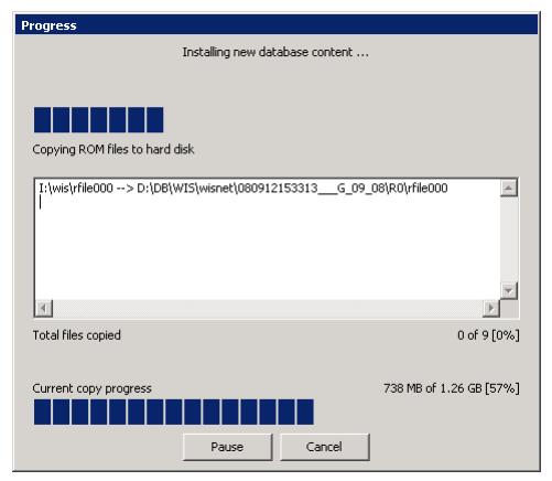
Please ensure that you choose computer systems that meet our requirements for the installation. You will find adetailed listing in Read more
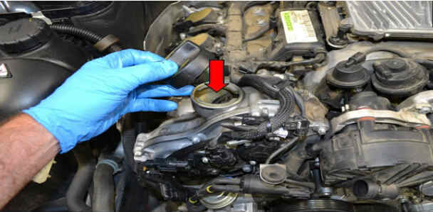
Frequent oil changes are perhaps the most important procedure you can do to maintain and prolong the life of your Read more
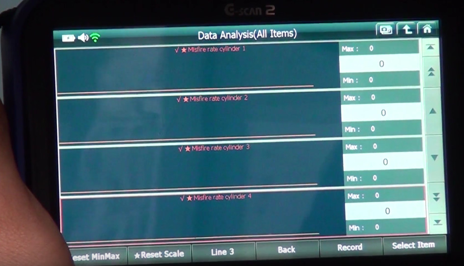
This article show a guide on how to use G-scan2
Please keep this link if you copy the post!